HOW TO DESIGN A REVERSE OSMOSIS PLANT IN 10 STEPS
Today, we will explain 10 steps of designing of reverse osmosis system. Chunke is professional RO Plant manufacturer from Guangzhou, China. We design over +1000 reverse osmosis water purification system for commercial and industrial application.
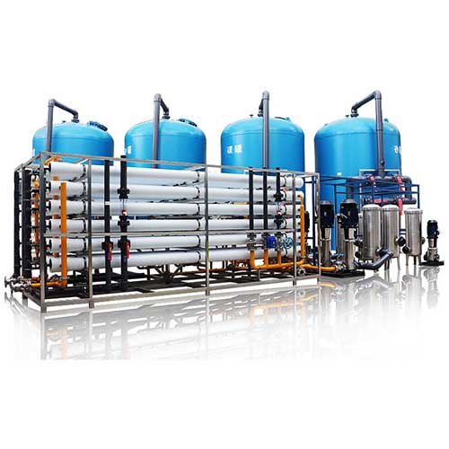
Now, we check step by step designing of reverse osmosis plant.
1. Evaluate Feed Water Source, Feed Water Qaulity and Treated Water Quality
As you know that in earth, only 2% of water is fresh water. All other water such as underground waters, river water, sea water, ocean water, lake water are not suitable directly drink or use in your application. Because these waters has dangerous inorganic and organic compounds, bacteria and viruses. So, we have to purify these waters. Test result is important for design a reverse osmosis plant.
You have water source, first you must know more about your water. The best way is send one bottle water to test laboratory in your city.
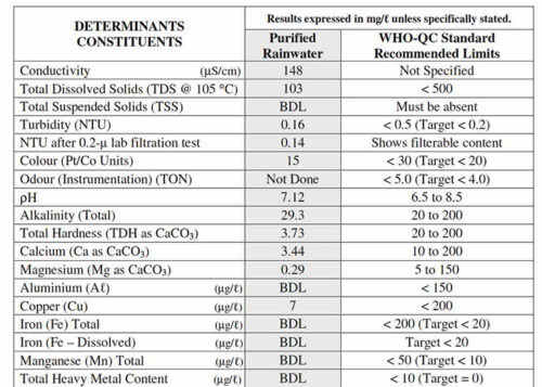
They give you an analysis result something like this. From this report, first check your TDS level. TDS means total dissolved solids, for more details about TDS, i suggest you to watch our this video. I put link below and here.
As regards to your application, which TDS level you want to achive for treated water. Such as if you use treated water for pharmaceutical industry, TDS level must be less than 1 ppm, if it is for irrigation, TDS level must be less than 500ppm, if it is for drinking, TDS level must be around 100-500ppm.
2. Determine the flow type
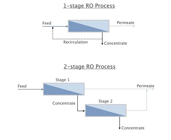
There are two flow types. Plug flow and concentrate recirculation.
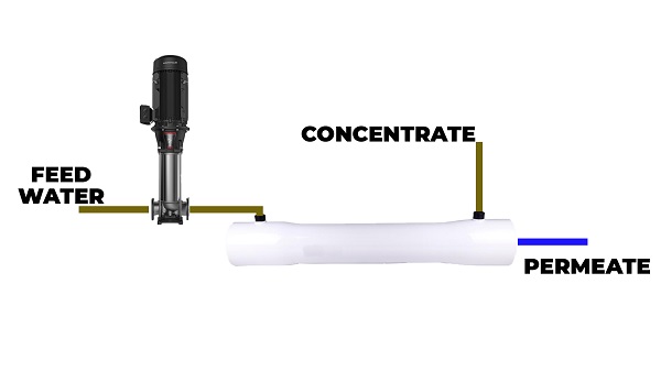
Normally, all of our systems are continues plug flow. In plug flow, feed water passes once through the system.
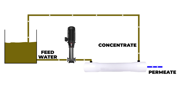
Here you see plug flow diagram. Feed water passes membrane elements, and you get permeate water and concentrate water. But sometimes, if possible, to increase permeate quantity and efficiency in all system, we send back concentrated water to feed water source. This flow type is concentrate recirculation. It is dependent on concentrated water TDS level, membrane recovery rate and membrane type. So, flow type is another important criterion design a reverse osmosis plant.
Here, you can see concentrate water recirculation type reverse osmosis system’s diagram.
Determine the flow type needs experience and technical knowledge.
3. Select Membrane and Membrane Type
In design a reverse osmosis plant, elements are selecting according to feed water salinity, feed water fouling tendency, required rejection and energy requirements. The first factor that has to be in consideration is the feed source. If the feed is brackish water, BW types ro membranes must be selected. If the feed is seawater, SW types ro membrane must be considered. TDS for brackish water is between 1000–15000 mg/l, and in seawater is morer than 15000 mg/l. Meanwhile, mg/l and ppm is same unit.
4. Selection of design flux
Water treatment companies are design a reverse osmosis plant as regards to specific permeate flow rate and recovery rate. Recovery rate means, how many per cent of feed water becomes permeate treated water.
The factor which has the greatest influence on the membrane system design, is the fouling and scaling tendency of the feedwater. To learn more about fouling and scaling, i suggest you to watch our video, in explanation section and here, i share the link with you.
A membrane system should be designed such that each element of the system operates within a range of recommended operating conditions to minimize the fouling rate and to help avoid mechanical damage. These element operating conditions are limited by the:
• maximum recovery
• maximum permeate flowrate
• minimum concentrate flowrate
• maximum feed flowrate

Here there is a table for flux rate, as regards to SDI (silt density index) some RO membrane manufacturers suggested flux rates, now we see how to use it. Such as you have well water, your SDI index is less than 3, your system average flux as L/m2.h is 22 -29. 22 is minumum flux rate and 29 is maximum flux rate, and maximum element recovery rate is 19%. These values are importeant design a reverse osmosis plant.
5. Calculation of module number
To calculate module number, we have to know:
· Permeate flow (Qp) (m3/day)
· Membrane active area, (Ae) (m2)
· Design flux, (f) (L/m2.h)
Permeate flow is your machine capacity, how many water do you need per a day. Membrane active area, you can get it from membrane supplier RO membrane specification and design flux L/m2.h, i already give to you in table.
After determination of the module type such as SW or BW based on the feed source and TDS, you can select from the catalog. You can get important information in the catalog such as specified performance, General product description, and product use, and restrictions.
For example, we use Dupont Filmtec BW30-400 element specification. I leave a link, also you can download from their official webpage. Here we see, active area is 37m2, permeate flow rate is 40m3/d, salt rejection is 99%.

Also here, membrane size you can see it. Diameter (C) is 7.9 inch, it is nearly 8 and lenght (A) is 40 inch. So it is called in market as 8040.
Now, we make one example. So, dont forget, if you design a reverse osmosis system 250 to 2000lph, you should use 4040 size lelement, 3000lph and more, you should use 8040 size element.
To calculate element number, it means reverse osmosis membrane number, we use this equation:
Equetion for number of element:
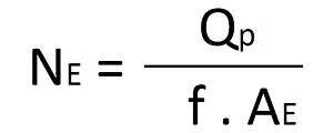
For example, we have well water, SDI index is less than 3. We check our table. Flux rate is 22-29, if you want to calculate maximum number of element,you should use 22, for minumum number of elements, you should use 29.
Such as we need water 6000 liter per hour. This is our permeate flow rate (Qp). Our well water TDS is higher than 10000ppm, it is brackish water, we choose BW type membrane. This is Dupont Filmtec BW30-400 element specification. Active area of element is 37m2 (Ae). Now, we use equation and put the number in equation for design a reverse osmosis plant.
Ne min= 6000/(37×29)= 7.3 = 6
Ne max = 6000/(37×22) =5.59 = 7
As you see, for 6000lph system, you can use 6 pieces RO membrane.
6. Calculation of Pressure Vessel number (Nv)
Total number of pressure vessels needed = (total number of modules) / (number of modules in a pressure vessel).
The calculated number should be rounded up to the nearest integer. Such as you find number 5.89, so you can use 6 vessels. For large systems, 6-element vessels are standard, but vessels with up to 8 elements are available. For smaller and/or compact systems, shorter vessels may be selected.
Small systems like 250, 500 liter per hour, just one 4040 or two 4040 element can be enough.
For example, if we go our 6000lph Reverse Osmosis System example, we found that we need 6 ro membranes, if we choose 2-element membrane housing, we need 3 membrane housing.
Meanwhile, Membrane housing and element vessels are same thing, every country using different term for it.
7. Calculation of recovery (S) %
Recovery is the ratio of permeate flow to feedwater flow, is calculated as this equation.

With increased recovery, the pressure may increase somewhat, but the brine will be more concentrated, which can make disposal more difficult.
In RO system, recovery is a function of salt rejection. So, the rejection capabilities of RO membranes are specified with either a percent salt rejection or a molecular weight cutoff (MWCO) value. Hence, salt rejection is typically used for RO membranes as this equation:
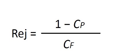
Abbreviation
· Rejection is dimensionless and (expressed as a fraction).
· CP = concentration in permeate,
· CF = concentration in feed water.
Rejection can be calculated for bulk parameters such as TDS or conductivity.
Maybe it is better to explain with an example how to use this equation in design a reverse osmosis plant:
Such as we have brackish water, its TDS is 12000ppm, and we want to get permeate water for irrigation as 500ppm. We use BW membrane and its salt rejection is 97%.
We have equation:

If you do not know how to use logaritmic and exponential number calculation, you can easily do with trial and error method, in this method, you give value to S, for brackish water system recovery rate between 0.40 to 0.70, so we start with 0.45, and we find 0.56 it means 56% recovery rate.
8. Calculation of stages
The number of stages defines how many pressure vessels in series, the feed will pass through until it exits the system and is discharged as a concentrate. Every stage consists of a certain number of pressure vessels in parallel.
Here, i will give you two tables for brackish water and seawater. You can use these tables to choose right stages number and recovery rate. But, normally we are using ROSA or WAVE software to be sure stages number.

9. Determine the ratio between stages (R)
The relation of the number of pressure vessels in subsequent stages is called the staging ratio we show it with R.
For a system with four vessels in the first and two vessels in the second stage, the staging ratio is 2:1. So, a three-stage system with four, three and two vessels in the first, second and third stage respectively has a staging ratio of 4:3:2. In brackish water systems, staging ratios between two subsequent stages are usually close to 2:1 for 6-element vessels and less than that for shorter vessels. Hence in two-stage seawater systems with 6-element vessels, the typical staging ratio is 3:2.
Hence, the ideal staging of a system is such that each stage operates at the same fraction of the system recovery, provided that all pressure vessels contain the same number of elements. So, the staging ratio R of a system with n stages and a system recovery S (as fraction) can then be calculated with this equation for design a reverse osmosis plant:
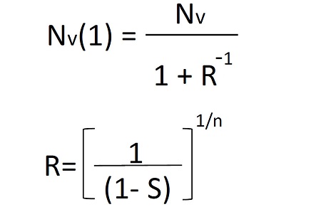
The number of pressure vessels in the first stage Nv(1) can be calculated with the staging ratio R from the total number of vessels Nv.
10. Balance the Permeate Flow Rate
The permeate flow rate of the last module of a system is normally lower than the flow rate of the first elements. So, this is a result of the pressure drop in the feed channel and the increase of the osmotic pressure from the feed to the concentrate.
Under certain conditions, the ratio of the permeate flow rate of the first element and the last element can become very high. These conditions such as:
· The high system recovery
· High feed salinity
· Low-pressure membranes
· High water temperature
· New membranes
The goal of design a reverse osmosis plant
The goal of a good design is to balance the flow rate of elements in different positions accordingly. This can be achieved by the following means:
• Boosting the feed pressure between stages
• Apply a permeate backpressure only to the first stage of a two-stage system
• Hybrid system: use membranes with lower water permeability in the first positions and membranes with higher water permeabilities in the last positions: e.g. high rejection seawater membranes in the first and high productivity seawater membranes in the second stage of a seawater RO system.
I want to tell again, If you design the system according to these steps, there is a probability that the designed system has some problems. So, it is necessary to analyze the system using some software such as ROSA or WAVE to fix the errors. Because as water treatment manufacturer, all systems, first, we check with software to see is there any design problem accordingly. It is very important, if you want to learn how to use these softwares, please write in comment.
To get more info about design a reverse osmosis plant, you can freely contact with us. If you need quotation, please fill in below form and we contact with you soon.

